Spiral Phased Array Antenna
Spiral Phased Array Antenna The Concept and Technology behind it.
papers used:
Scalar Waves: Theory and Experiments
Classical Superposition of Waves to Quantum Interference
Mitigation Reflections from Antenna Spiral Arm Ends
A Systematic Approach to Improving the Performance of Spiral Antenna
Wideband Novel Modified Archimedean Spiral Antenna Array
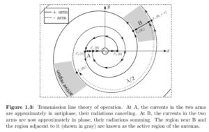 After very long research and experimentation on the 5-8Mhz range, we have designed an Archimedean multiphase antenna to be used as a stickpad and/or broadcaster for the specified frequency range, although it could broadcast almost to any range up to 200Mhz it has been calculated and optimized for the range of 5-8Mhz. In my research we have calculated both Archimedean and exponential spiral patterns both have pros and cons.
Although Archimedean and exponential spirals have different equations defining them, research shows that their characteristics do not differ by very much. The Archimedean spiral arm lengths can be long and produce high circuit losses at low frequencies. The wrap angle of an Archimedean spiral changes from a high value in the center to a low value on the outside. The high wrap rate in the center excites more higher-order modes at high frequencies. 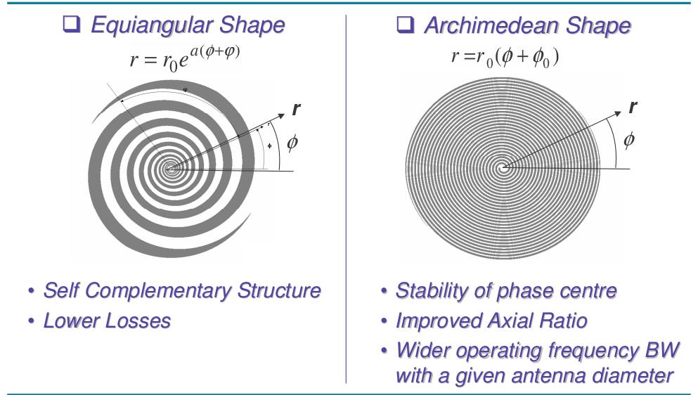 The low wrap rate at the outer diameter improves pattern shape at low frequencies. Although an exponential spiral has more uniform characteristics over the entire frequency range, an Archimedean spiral is more useful to my goal of shortwave transmissions of the 5-8mhz range.
The low wrap rate at the outer diameter improves pattern shape at low frequencies. Although an exponential spiral has more uniform characteristics over the entire frequency range, an Archimedean spiral is more useful to my goal of shortwave transmissions of the 5-8mhz range.Spiral trace size,gap, and spiral number where calculated, along with proper positioning on an 4 layer pcb stack development.4 layer means 4 perfectly calculated spirals stacked together with a tiny small capacitive dielectric layer between them so they can create the perfect scalar creation and emission device. But the most tricky part was the spiral feed bridge.
The feed bridge is the center of the spiral that needs to be either resistive or capacitive depending on the needs of the broadcast F-Range.Taking as granted(but tested both) that capacitive feed bridge is the one that works best for the hertzian to scalar transfiguration. The capacitors values where calculated using using the Pythagorean Golden ratio φ=1.618 so their difference would be close to the φ as much as they could, those values on pf capacitance where to hard to find on the market. Capacitor material was also important as plain ceramic smd’s where cutting the oscillations by 1/8. Only high quality RF capacitors and mica dielectric ones where working properly. After a lot trial and error and theory errors we have managed to create the best possible scalar emission antenna for radionics purposes.
Near field phase “collisions” are best way to create non hertzian-scalar waves.
Results are astonishing!
The theory behind all this it is described on papers, and the links are at the top.
Notes:
Frequency spectrum calculations, Φ calculations and others made with Matlab .
PCB designing and blind vias circuit with altium.
Spirals originally made with solidworks.